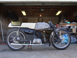
Saturday, November 22, 2008

More Tires, and Red Wheels

I've been busy working on my Formula Vee race car, and haven't given Salty much attention lately. Well, that changed this weekend. I received two more of my back-ordered tires (only one more rear tire remains) and set about getting them mounted up.

Installing a new front tire on the chrome front wheel rim, in the living room, while Susan watches Dancing with the Stars.


Last month, I had assembled a second set of wheels, using an older pair of wheel rims whose chrome was not in fantastic condition. I decided to paint the rims red, to match the tank and seat. I wasn't sure if I would like the end product on the bike, but figured what the heck!

Installing a rim band on the red wheel rim, before the front tire gets wedged on:


A note about installing tires. I don't have any fancy tire installation tools, so instead I use a pair of old screwdrivers that I've smoothed over on the end and edges, and a couple paint can opening thingies. You know those little guys that looks like a bottle opener, but have a small lip for getting paint can lids open. I also use some warm soapy water, and take my time. After a few tires, I've gotten pretty good at it.

And here is the half finished product, with a red wheel on the front:


I also had to make a new exhaust bracket, as the right side cover of the C100 3-speed engine has a little "bump-out" for the automatic clutch. Luckily I had more than enough room to move the exhaust out a tick to clear.

After I get the new engine built for the FV, I hope to get Salty up and running. Possibly over the long Christmas weekend.

C'

Sunday, October 26, 2008

Test Engine Assembly and Mockup

I had a little time this afternoon (after a nice birthday lunch) to assemble the "test engine." This engine uses the 3-speed auto clutch from a C100, but with a higher compression C110 piston and the bigger port aluminum C110 cylinder head. The cylinder barrel and rocker box assembly are shared between the C100 and C110.


Right side of C100 Test Engine


Left side of C100 Test Engine


And of course I couldn't wait to get it mocked-up in the frame, to check the fit of the exhaust and intake manifold/carb setup. As it turns out, the "right" side engine case is slightly different between the C110 and C100. The C100 has an extra buldge on the clutch side because of the automatic clutch mechanism. This buldge hits the exhaust pipe I built. Just enough so that the exhaust won't bolt on the swingarm bracket. I have a couple options, the easiest being to extend the exhaust bracket, but I'm fearful that might make it look funny if it starts to "run down hill" as it exits the back of the bike. I'll need to spend some more time fiddling with it. Hhhmm.


Test engine installed, intake and exhaust mocked up on bike for fitment


Little Salty is really starting to look like a bike now


Another productive and fun day in the garage.

C'

Saturday, October 25, 2008

Silver Side Covers

After a bit of photoshop work, I decided I liked having the side covers painted silver. So...I painted them silver yesterday. Exciting I know!

Silver side covers. The end.


After some work porting formula Vee cylinder heads, I'll get back on Salty. I should have one of my cylinder barrels back from the machinist, and will assemble the "test" engine.

C'

Monday, October 20, 2008

Front Fender Fun

All it takes is a little paint, and suddenly little Salty starts to look like a motorcycle. I prepped and painted the front fender over the weekend, and got it mounted up late last night. I just couldn't wait to see what it looked like.

It took a bit of fiddling to get the fender to fit just right, as it isn't the original C110 front fender. I'm not actually sure what it came off of, as it was just sitting in my spare parts bin. It looks the part and will keep salt spray off the engine when bombing along at 50mph.


Freshly painted front fender mounted on bike:


Close up of the front fender, still needing a good rubbing out and polishing:


Lastly, I test fit the side covers. The "left" side covers up the battery, while the "right" side covers up the air filter. I'm not yet decided on the final cover. I shot them black primer just to see how black would look, but I don't like it. Perhaps silver will work for them. hhmm.........


C'

Saturday, October 18, 2008

New (and cleaned up) Engine Parts

I spent some time today cleaning up engine parts, mostly top end cylinder head parts like rocker arms, valves, springs, pushrods etc. I also took the opportunity to lighten a couple sets of just about every component. My goal is to have two complete running engines, and enough spare parts to rebuild each engine if needed.

I'm building up the original C110 4-speed along with a C100 3-speed. The C110 will have all the hot rod light weight parts, while the C100 will get mostly stock parts, and end up being the test mule over the winter and spring.

Two sets of lightened rocker arms:


A few sets of valves. The back set is stock, the front three sets have been backcut and lightened around the tulip:


One of two sets of brand new 40mm C10 Piston Kits I found, complete with pin, rings, and pin clips:


10-Pack of "O-Rings" kits. Seal the cylinder head to cylinder barrel, around the pushrod openings:


After I assemble a rocker box and cylinder head, I'll assemble the C100 engine and get it mounted in the frame.

C'

Monday, October 6, 2008

Garage Organization

This falls under the "not really Salty related" but at least I'm better organized category.


My Pops gave me the red chest of drawers on the left, the bottom section. So I moved my bottom chest to underneath the work bench to house those small odds and ends that always get lost. I also added a bunch of small shelves underneath the center bench to store typical power tools like drills, grinders, and torque wrenches. I had a bunch of wasted space before this. Not really all that pretty, but at least I can find most of my tools now!

C'

Building an Intake Manifold

After getting the Monster Carb in the mail on Friday, I set about building an intake manifold for it. I had sketched up various ideas, and settled on a system design I was hoping I could build at home, without needing to outsource all the fun work.

The concept uses two large washers, one for the flange that connects to the cylinder head, and one for the flange connecting to the carb, connected with a section of curved pipe massaged to fit the proper openings of the head and carb. With washers and pipe in hand (and a cold beer for refreshment,) I got busy.

Washer on left fits cylinder head, washer on right fits to carb. Note that carb mounting holes are slightly off centered "up and down" in relation to the center hole:


Center pipe section is cut from a conduit sweep. I cut four little "pie sections" out of the cylinder head end so the pipe could be made slightly smaller in diameter to fit smaller intake port opening:


Small end of pipe was formed, welded, and ground smooth:


Freshly welded intake, ready for high heat resistant paint, followed by a good wrapping of exhaust header wrap for better thermal properties:


Carb mounted on intake. Intake bolts are threaded into the flange, which was tapped before painting:


Overall, this was a fun project to work on, and is sized to work with several typical small Mikuni carbs, which all have slightly different flange bolt patterns. I also made a second set of flanges, and have enough of the conduit sweep remaining to build a second complete manifold.

C'

Saturday, October 4, 2008

Sneak Peak!

Just a quick sneak peak of the bike as it is getting assembled into chassis form. The paint is a little dull and dusty, since it hasn't been rubbed out yet.


Monster Carb

A small package arrived on the front porch this afternoon, while we were off picking up key project items (book shelf, salad bowls, and new shoe baskets) from Ikea. It contained a brand spankin' new Mikuni VM24. That's right, 24mm, or about the size of my big toe.

Compared with the 16mm carb that came on the C110, and the 13mm carb that comes on the C100, this VM24 is indeed a monster.

VM24 uses a 48mm bolt spacing "hot side" flange


A simple hose connection will be used on the inlet side


I've already mocked-up an intake manifold to get the positioning of the carb correct, in relation to the engine and intake connection on the frame. The net step is to actually fabricate the flanges for both ends, and create the center pipe, which will be both tapered and bent in a 70-degree smooth arc.

C'

Sunday, September 28, 2008

A Little Bit of Paint

I got busy priming and painting the past couple of weekends. Last weekend, I worked on the gas tank and seat, which got sprayed bright red. This weekend, I added some silver to the main frame, front fork, rear swingarm, and a few small brackets and accessory items.

A few items painted


The last big item that needs paint will be the front fender, which needs a bit more body work to get it ready for silver paint. And of course the side covers, and some more brackets etc. I guess I better make a list!

Just for fun, here's another photo of the rear tire, a IRC NR53, as mounted on a back wheel.


I also spent some time today mocking up an intake manifold. In fact, my mock-up may end up being my final product. After I clean it up and lay on some heat resistant paint, I'll snap a picture.

C'

Wednesday, September 24, 2008

Front Sprockets

As mentioned in the last post, I need to "gear up" the bike in order to see speeds over 52mph, the rating of the bike at 10,000rpm with stock tire and gearing. The slightly taller rear tire will help a little, but I knew I would need to make changes to the sprockets. In stock fashion, the bike uses a 14T front sprocket and a 40T rear sprocket, giving it a final drive of 2.85:1.

I began searching for bigger front sprockets, but found it difficult to find items marked for use on the C100/110 engine. Most sprockets are tagged for XR50s, or CT70s etc. I got lucky the other day and found a Honda Passport (C70) site that gave a listing of other Honda models that used the same sprockets. It included the C100, along with a dozen other small Hondas like the CL70, XR80, ATC70, S65 etc.

So, I started searching for sprockets for some of these other Honda models. I came across Beatrice Cycles ( http://dratv.com/index.html ) which happens to have an excellent breakdown of parts, categorized by model and major component. If you want electrical parts for your ATC110, they've got it. Likewise suspension parts for your Z50.

I searched around the C70 page, and found that they offered 15T, 16T, and 17T front sprockets. I bought one of each, along with a few extra tire tubes (for the red wheels.) Everything arrived at my door within 3 days. I quickly ran out to the garage and confirmed that yes, these sprockets do fit the early pushrod motors.


From L to R: 14T, 15T, 16T, 17T


Based on my gearing calculation spreadsheet, these sprockets should give me a range of speed from 55 to 67mph in 4th gear at 10,000rpm. I plan on building up both the C110 4-speed engine, as well as a 3-speed C100 engine, which has a slightly shorter top gear.

Perhaps I'm spending too much time worried about this one subject, but given the fact Bonneville is at much higher elevation, I wanted to have plenty of options for fiddling with gearing. A few hundred rpm could make a difference, especially when your only dealing with 5.5 to 6hp!

C'

Monday, September 22, 2008

Assembled Wheels, Chopped Tail, and New Tires

Over the past few weeks, I've ordered an assortment of parts for Salty, ranging from NOS Piston kits, to larger front sprockets, to a couple sets of tires. This post will focus on the tires, and their fitment to the bike.

One of the "speed modifications" to this little bike is to gear it up. In stock form, the bike runs a 14-tooth front sprocket, and a 40-tooth rear sprocket, with a 2.25"x17" rear tire. Based on some calculations I've put together, this should put the top speed around 52-53mph at 10,000rpm. Perhaps I'm hugely over estimating the performance of the bike, but I wanted gearing options that would let me run at least 60mph.

One of the easiest solutions is to run a taller rear tire. That isn't a simple matter when it comes to small bike tires, however. I want to keep the tires fairly narrow too, so after much research I found the Michelin Gazelle M62 tire. This is a small motorcycle/moped tire that is speed rated to 82mph. It is available in several sizes, including a 2.25x17 (front) and a 3x17 (rear.)

However...nobody had any of these tires in stock. I talked to several vendors, and ended up having orders sitting around for more than 2 full months, with expected delivery dates getting pushed out further as each week passed by.

So, I researched more and came across the IRC NR53. It is a semi-slick treaded tire, again made for small motorcycles and mopeds. It too is speed rated, and offered in both a 2.25x17 and 2.75x17 size. I placed my order and within days I received one of four tires. I ordered two fronts and two rears. The other three tires are on back order, but hopefully might actually get shipped sometime this year!

I quickly mounted up the 2.75x17 rear tire to the rear wheel assembly I had put together. I'll call these the "chrome wheels" since I'm using a set of stock wheel rims with pretty decent chrome. I knew there could be some clearance issues under the rear fender with this wider rear tire, so I chucked it under the bike to see how bad it would be.

As it happens, I also took an opportunity to trim the rear fender. As the rules state, there can be no rear fender extending past the centerline of the rear wheel, but the seat can essentially act as the rear fender, which mine will. Sorta. The exact rules reads as:

...
5.F. FRONT AND REAR FENDERS
Front and rear fenders may be removed. Generic, replacement type
fenders may be substituted. Rear fenders may not extend beyond
the centerline of the front or rear axle. Elongated seat may act as
rear fender and is subject to scrutineering.
...

So, I grabbed the cutting wheel and shortened the rear fender. Don't worry, lovers of originality, as I have several stock rear fenders sitting on the shelf from parts bikes ready to go on should I ever want to take it back to the original full-fendered look.


Rear tire mounted up, and rear fender shortened per rules:


As it sits, I barely rub when I'm fully loaded on the bike, at its lowest settings. It is barely rubbing on the edges of the tire. With just a little "spreading" of the rear fender - what's left of it - I should be able to go off-roading without rubbing.

In preparation for the other set of tires arriving, I put together a second full set of wheel assemblies this past weekend. We'll call these the "red wheels" since I painted them red to match up with the red tank and seat (more on that later.)

Second set of wheel assemblies, sittin' pretty waiting for fresh tires


Tommorow, I'll post about my newly found set of front sprockets.

C'

Friday, September 12, 2008

Leathers!

One thing I needed to find before any running with this bike, was a set of suitable leathers, boots, and gloves. Per the rules, and general "rule of thumb for Bonneville," I looked for all leather construction, without much perforations across the front and in other critical areas. This seems to be the key, as many track day leathers use perforated material across the chest, and under the arms for ventilation. I didn't really need to pickup anything quite this soon, but I've been keeping an eye out for items locally.

As it turns out, I came across a set that seem to fit the bill, for a good price. They are a two-piece set of Sinsalo leathers, full leather construction, dual zippers at the waist, that fit me well. A tad snug in the legs/knees, but I am comfortable while in the tucked position. They also came with a set of full leather boots and gloves, both of which fit perfectly.

Captain America Returns!


Fully Tucked and Ready for Speed


All I need now is a suitably rated Helmet. My SA2005 Helmet I use for the Formula Vee is not M rated, and has a much smaller field of vision. So the search begins for a M2005 helmet...

C'

Tuesday, September 2, 2008

Building an Exhaust

One of the items I still needed to build was an exhaust system. Per the rules, the exhaust couldn't extend past the rear tire, and it's opening couldn't be directed at the rider, or the salt surface. Unlike 2-strokers, you don't have to design an expansion chamber to produce power at a certain RPM for a 4-stroke. However, there are still some basic calculations that can be run to optimize length and diameter, based on RPM. Also, stepped designs can be taken advantage of.

These calculations called out for a main header pipe roughly 18-inches in length, and a diameter matching that of the stock header pipe. So I grabbed a spare header pipe, added a few inches to it, and came up with my 18-inches exhaust length. Unfortunately, this ended the exhaust just ahead of my foot, and looked rather incomplete.

So taking advantage of a stepped design, I used a piece of larger diameter pipe to bring the exhaust back behind my foot, then built a simple megaphone that attached to the end. The megaphone was rather fun to build, as I simply cut out a pie shape wedge from a piece of 2 inch pipe, then shaped the leftover piece into the cone shape, welding along the seam.

In the end, I'm left with a main header pipe to match up with my RPM zone, that is stepped up and mated to a megaphone for looks. a simple hanger is attached to the front swingarm bolt. The entire thing will get coated in trusty bbq paint, and possibly wrapped in header wrap. A few photos are shown below.

Proportions fit the profile of the bike pretty well


The header pipe actually runs inside the "stepped-up" section of pipe about 6 inches, for a total primary length of 18 inches.


Megaphone was "squashed" to produce an oval section. I might give the tip a slight slash cut.


Chris H.

Thursday, August 21, 2008

Front Fender Fun

After sorting through my bins of random spare front fenders I've pulled off parts bikes, I came across a scabbed up unit off a 1965 Suzuki K11. It has the same full fendered lines of the original C110 fender - which didn't come with the bike - and the same basic proportions. After a bit of measuring, and test fitting, it looked like it would be a good match up.

I only had to drill two new holes for it to mount to the front fork tubes, and shorten the little rear stays that support the back of the fender. It will obviously need a bit of body work, as it was rather dented and skinned up, but I like the overall look of it.


Suzuki K11 front fender mounted up easily, allowing for full suspension travel with no rubbing.


Easily mounts to upper front shock bolts


Should help keep the salt spray down


Chris H.

Monday, August 18, 2008

Making a Seat and Gas Tank Extender

One of the keys to building this bike was to keep it somewhat "period correct" with regards to modifications. I was hoping to build it like it would be built back in the 60s. One of the main items I knew that would need to be built or modified would be the gas tank and seat. The seat would obviously need to be made to accommodate my skinny butt when tucked down in my Bonneville speed demon posture. That means there is a huge gap between the seat and tank.

Option 1 is to buy a reproduction tank like on all the vintage road race bikes. Something like the tank on a CR110 Honda immediately comes to mind. Besides the fact a reproduction tank like that costs more than the entire bike did, I didn't entirely like the look of it. Well, I loved the look of the long skinny tank, but it just didn't fit in with the hot rod theme I was going for. Besides, the stock tank was decent, as were the chrome panels and rubber knee pads. Option 2 is to build a tank extension. Basically, a fake extension that would fill up the gap, but also be strong enough to support me laying my belly and chest on it, and support the grip from my knees as I squeeze down on it when tucked.

I decided to go with option 2.

Having made a similar rear seat section for the Bridgestone 90 Racer project, I had an idea of the generic size and proportions.

Photo of the Bridgestone rear seat section for reference:


I started off with a cardboard template, to get an idea how big the final product would need to be. I then got to cutting and grinding and drilling and welding, and made up a very simple frame that mounts to the bike using the rear gas tank hold down bolt, and the upper rear shocks mounts for support. It is basically a 1" angle iron craddle that the tank extension/seat will then bolt to, and then be able to be removed as one piece.

With dimensions in hand, I visited the local craft store for some crafters foam. These foam blocks are available in various sizes, and as it turns out these little brick shaped pieces matched up with the width and height I was looking for.

Using a scrap piece of wood, I glued and screwed the foam blocks to each other, then to the wood in a rough shape. I then proceeded to carve and sand the foam into the shape I was looking for. It had a little bit of taper from bottom to top, and I made the rear portion of the seat have the usual cafe' racer bubble shape.

Foam bricks carved and sanded to shape:


After the foam mold was shaped to satisfaction, I got out the fiberglass and resin. I precut about 4 layers worth of cloth, using both 8 oz bi-directional weave and some thicker chop mat for added thickness. It was a fairly warm day, so I had to mix the resin in smaller batches and work quick. I wouldn't say it was the best job I've ever done, but I knew it would require a lot of finish work anyways to make it smooth and pretty.

After it setup, i popped the mold off the wood, and removed the bottom layer of foam bricks. This was the underside of the part, which would get mounted to the angle iron base. I then added a few more layers of fiberglass to essentially create a honeycomb of fiberglass and foam. The main section of the tank extension, and the rear tail bubble are completly filled with foam, and surrounded by fiberglass. the result is a very strong and stable part that can support some weight.

I then trimmed the part using some basic angle grinders and thick sheet metal sheers. I gave the bottom edge a little shape to match up with the rubber knee pad on the stock gas tank, while keeping the bottom edge just tall enough to completely hide the angle iron frame work underneath. After a bit of final grinding and fitting, I mounted the seat to the frame work, and then mounted it to the bike.

Raw fiberglass part on bike for test fitting


I let the part setup for a couple weeks before I started to do some finish body work to it. Using some good 'ol fashion body filler, I was able to clean up the surface. Luckily I still had my body filler scrapers in the toolbox, since the easiest time to do rough finishing on filler is right after it starts to setup, as it can be scraped off like a cheese grater, in little shavings.

Filler is a pain in the butt to sand, so anything to minimize sanding is worth it


It still needs some finish work in a few sections, but you can see the overall look of the tank extension and seat as it is mounted on the bike. I cut out a piece of 1/2" thick foam rubber for the cushion, which will just be spray glued down to the seat pan, with four small holes to access the bolts that secure the seat to the frame work underneath.


Here is a shot with the intrepid rider on board showing off his not-so-legal slippers and boxer shorts:


I'm still contemplating the next project, but I'm thinking it might be a small front fender to help keep the salt spray off the engine, bike, and rider.

Chris H.

Sunday, August 17, 2008

Fun with Scales

In preparation for the engine build, I picked up a US Balance Magnum 1000XR digital scale, so I could weigh all the little parts and have a baseline. The scale has a max capacity of 1,000 grams, with 0.1g precision.


After cleaning up all the parts, I weighed everything in the top end of the motor.

Engine Parts weight (grams)


Piston 80.1
Piston pin 20.9
rocker arm shaft 12.8
small rocker arm 28
big rocker arm 34.7
rocker arm shaft spring 1
top piston ring 2.6
middle piston ring 2.6
bottom piston ring 3.1
short pushrod 15
long pushrod 15.7
intake valve 15.8
exhaust valve 17.9
inner valve spring 6.3
outer valve spring 15.8
keepers (pair) 0.8
retainer 4.7


I intend to build up a couple different engines for this project. I figure one will be a mild hot rod setup, with some basic lightening of components, increased compressions, bigger carb etc. Then a high test hot rod motor to eeck out that last 0.5 to 1hp.

Chris H.

Footpegs, Brake Lever, and Rear Shocks

With the front handlebars in place, I was able to stretch out on the bike and get an idea of where I wanted to mount the rear foot pegs and rear brake lever. I figured fitting my lanky 6-foot tall frame on this bike could be a challenge, so I wanted to see how uncomfortable I would be using the stock passenger foot peg locations. As it turned out, it felt great. It gave me a good tuck, just enough clearance between my legs for the tank extension, and my feet/ankles didn't feel too cramped up.

Getting an idea where to mount the rear footpegs.


With the footpeg location selected, I then turned my attention to the rear brake lever. I had given thought to using a cable, but decided that an easier solution would be to simply modify the stock brake pullrod, and of course make a new lever. As it turns out, there is a boss mounted to the backside of the swingarm that locates the front of the rear brake/hub stay. So I got crafty and built a new lever

Simple lever cut from single sheet to minimize joints. 1/4" rod was welded to backside of plate to add stiffness. Entire lever pivots on the swingarm boss, pulling the shortened brake pullrod in a forward motion, just like stock.


As mounted on the bike, mostly hidden behind the swingarm.


I then scrounged through the spare parts bins and found a set of matching footpegs off a C100 that threaded right into the stock swingarm posts. The toe kicker for the brake lever is a passenger footpeg off another parts bike.


Brake lever, footpegs and toe kicker fitted.


Lastly, I decided to work up a set of rear shocks, as I was tired of having to carry the back of the bike around when I wanted to move it in the garage. I had taken dimensions of the little front shocks used in the leading link setup, and decided to see if could be used on the rear. The benfits would include having the same shocks on all "four corners" and since it is a nice little coilover setup, I could change spring rates or heights to best suit the bike.

Set of stock C110/100 front leading link shocks used in the rear. Like the front setup, I have about 1-inch of bum travel with my weight on the bike, with lots of adjustability should I want to change it.


Chris H.